|
|
|
|
|
|
|
Cockpit – 2001
|
||||
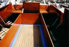
We decided to re-do the cockpit because we wanted to relocate the gas and water tanks, we needed to repair a few ribs, and because the cockpit teak was worn thin from years of use, and would no longer hold the bungs covering the fasteners in high-traffic areas. We installed a new gas tank that lies partially under the cockpit sole (rather than on top), freeing up more locker space; a new water tank was installed under the forward V-berth. New cockpit framing was designed to fit the new gas tank location, to allow access under the cockpit for maintenance, and to improve the cockpit lockers. The cockpit sole teak was resurfaced to a uniform thickness and relaid on the original plywood with epoxy. The seams between the teak strips were filled with 3M teak seam sealant. The L-shaped teak border was resurfaced and also bedded with the same 3M sealant. Two new cockpit drains were installed. The counterbores for the cockpit drains and bronze access cover to the stuffing box and transmission were recut with a router using a circular guide. The cockpit sole is mounted along the perimeter through the L-shaped borders into the framework; the center is mounted through the bronze access cover and under the compass stand. |
||||
|
|
|
|
|
|
|
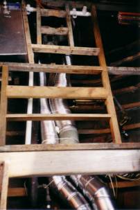
1. Revised cockpit framing. New fuel tank and new engine compartment ventilation system installed |
|
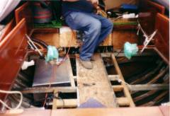
2. Cockpit chaos – gas tank and framing installed – much left to do…
|
|
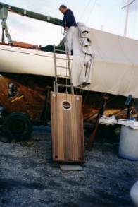
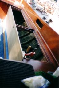
3. Bringing up the rebuilt cockpit sole… |
|
4. Cockpit sole laid in position |
|
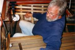
5. Installing “ceiling”. These slats keep contents of lockers away from the hull for good ventilation. |
|
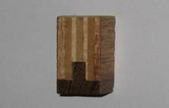
6. A slot was cut in the 5/8” mahogany plywood, and a piece of teak was cut into a “T” shape and epoxy glued to the bottom surface of the plywood to seal the end-grain. This was done along the entire bottom edge of the cockpit sides to prevent water from seeping into the end-grain of the plywood. |
|
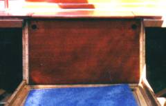
7. Aft cockpit wall installed, stained, and sealed with Pettit clear sealer. The cockpit sides will be epoxy-glued into the channels cut in the aft cockpit wall. The bottom side and edge of each wall fits against the L-shaped teak piece on the cockpit floor; they will be bedded with 3M teak seam sealant. |
|
8. Installing new cockpit sides. The front edge of each side is epoxy glued to a clamp that is glued to the forward bulkhead. A 3/16” mahogany overlay was installed on the forward bulkhead between the cockpit sides. |
|
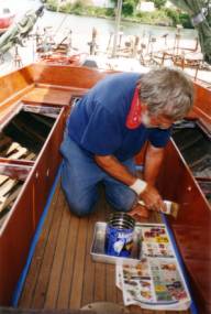
9. Varnishng! |
|
10. New sides installed and varnished. The round holes are for water drainage from the channels that run between the cockpit seats. The undersides of the hinges are sealed with thin rubber strips that direct water that leaks through the hinge into these channels. The round holes are 1” diameter copper tubes cut flush and epoxied to the cockpit side and the channel, preventing water from seeping into the plywood end-grain. |
|
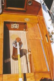
11. Instrument panel, winch handle mounts and engine controls all installed. The compass stand is easily removable for varnishing; the mounting screws and electrical wire tube are sealed with o-rings. No bedding compund is required. |
|
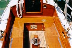
12. Finished! |